We are today so familiar with the word computer, that we barely bother to ask the question, what is a computer?
You may be surprised to know that a computer in the 1920s would have been a person sitting in the corner of an office, whose job it was to perform calculations on paper. Humans can be slow, unreliable, make mistakes, need lunch breaks and expect salaries. It wasn’t long before companies decided to replace them with machines.
You may remember the GCSE definition of a computer being something like this:
A system comprising input, processing capabilities and output
An electronic circuit comprising a few switches to input a binary number, a processing circuit, and a light emitting diode (LED) that comes on only when the input is a prime number, could match the definition of a simple computer system. Typically there will also be some memory. Hence at GCSE we learned about CPUs and types of memory, as well as binary.
(Recap)
Activity 1
Read the article here on early computers, be prepared to summarise verbally what you have learned. You do not need to read past 1983. In particular make notes exploring the following questions:
- What is a stored program computer?
- When did keyboards become an input device for computers?
- What size was a typical computer in the 1950/60s?
- When did transistors first appear inside computers?
- What is a central processing unit?
- What was significant about the IBM PC?
(Whole class discussion)
Activity 2
Use this website to build the symbol for any of the following gates
- AND gate
- OR gate
- NOT gate
Use the clear button to erase what you built, and then create one more symbol by choosing from one of the two remaining gates.
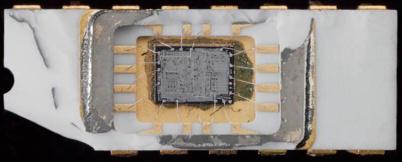
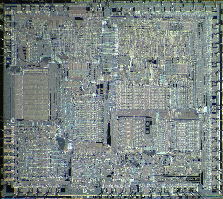
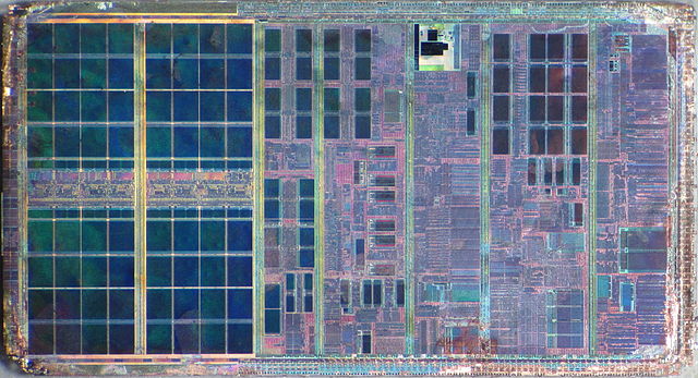
Integrated Circuits
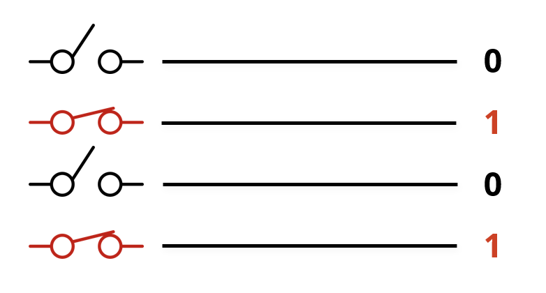
Transistors are the building blocks for electronic circuits in modern computers. They perform the function of a switch, allowing a current to flow (ON, or TRUE or 1), or not to flow (OFF, or FALSE or 0). Hence they are perfect for digital computers, which encode everything as 1s and 0s.
A collection of transistors can be configured to form a gate, for example an OR gate, and several gates can be connected together to form a more complex circuit, examples might be:
- a memory circuit that will store one bit
- an adding circuit that will add together two binary numbers
It is possible to put lots of individual digital circuits together into quite complex architectures. Ultimately you can produce an entire computer system using transistors as the fundamental component.
Circuits using transistors became smaller and smaller over time. These could then be placed inside a single package which we commonly refer to as an Integrated Circuit (IC). Central processing units eventually became shruken down onto a single IC. Early CPUs such as the Intel 4004 had a few thousand transistors. Today a CPU might contain over 1 billion transistors.
The Bus
A circuit may often deal with groups of bits. These bits might need to be passed from one place to another, for example from the CPU to memory. For this reason, we often see in digital circuits, groups of wires running in parallel across the circuit carrying binary signals. We call each group a bus.

Specifically, there are three types of bus on a typical computer system’s motherboard:
- The address bus – the CPU uses it to specify an address to read/write
- The data bus – used to transport values between CPU, IO and memory
- The control bus – other signals that are necessary for system operation
- Bus Request: “I want to use the data bus!”
- Bus Grant: “Go ahead and put your data on the data bus”
- Memory Read: “I want to read data into the CPU from memory”
- Memory Write: “I want to output data from the CPU to memory”
- Interrupt Request (IRQ): “CPU, stop what you’re doing, I have something urgent that needs dealing with!”
- Clock: synchronises all read and write operations
For an example of how we might use a bus, we might want to send a 4 bit binary number to the CPU on the data bus using switches. A closed switch would send a one, and an open switch would send a zero.
It’s up to the designer of a system to decide how “wide” a bus is – i.e. how many bits it should have. Typical data buses these days use 32 or 64 bits – that’s a lot of wires!
The FDE Cycle
The CPU can be divided into two logical units:
- Control Unit
- Arithmetic and Logic Unit
Within the Control Unit, a process called the Fetch-Decode-Execute cycle takes place. Where instructions are fetched from memory (either ROM or RAM), made sense of by the CPU, and then executed. A group of special purpose registers inside the CPU are used during this process. They are:
- The Accumulator
- The Program Counter
- The Memory Data Register/(Memory Buffer Register)
- The Current Instruction Register
- The Memory Address Register
Activity 3
With a partner, one of you describe the diagram below to your partner who must draw it only by listening to your description (i.e. they can’t cheat and look at the diagram on this screen!)

Once it is done, swap around and anything that needs correcting should be described by your partner, and you should make the corrections.
Swap around one final time to check that the diagram is now complete and correct, if not describe the corrections again.
Activity 4
Annotate the CPU part of the diagram to show the interaction of the special purpose registers in the CPU. You may use this resource to see the detailed operation of the FDE cycle.
(Discussion on arrows inside the CPU and on buses)
Knowledge Check
- With which component is a modern CPU implemented?
- What is an IC?
- How many wires are on a bus?
- How many lines do you draw when drawing a single bus?
- Which buses tend to be bidirectional?
- Name 5 signals on the Control bus